

Let’s get started with this innovative project where you will learn to create a simple Hand Gesture Controlled Robot. You will be interfacing the MPU6050 sensor, RF Transmitter-Receiver Pair, and L293D Motor Driver with the Arduino board. Transmitter and Receiver sessions are separated on the robot. The receiver circuit is the same as in the RC car projects whereas you need to program the transmitter circuit to send hand gestures as commands to the receiver part.
Components Required
- Arduino Board
- Bread board
- RF Tx-Rx Pair
- L293D
- MPU6050 Gyroscope sensor
- Battery
- Connecting wires
- Robo car chassis
- HT12D IC
- HT12E IC
- DIP Switch
What is the FS1000A RF Module?

The FS1000A is a 433 MHz RF transmitter and receiver module is a pair of small RF (radio-frequency) electronic modules that are used to send and receive radio signals between two devices. The data is sent by the transmitter module from the transmitter end, and it is received by the receiver module at the receiver end.

This tiny module is the transmitter. It is as simple as it appears. The SAW resonator, which is tuned for 433.xx MHz operation in the module. There is only a switching transistor and a few passive components.
When the DATA input is logic HIGH, the oscillator runs, producing a constant RF output carrier wave at 433.xx MHz, and when the DATA input is logic LOW, the oscillator stops. This is known as Amplitude Shift Keying.
HT-12E
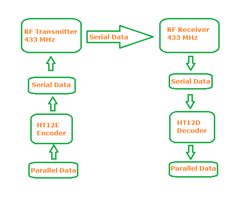
It is an encoder IC that converts the 4-bit parallel data into serial data in order to transmit over RF link.
| Pinout |
|
| VCC | Used to supply power to the RF receiver module. The supply voltage is 3V-12V |
| GND | The module's ground pin. Connect it to the GND pin of the controllers and encoder/decoders. |
| DATA | This is the transmitter's data pin. It receives data from the microcontroller or encoder and transmits it to the antenna. |
| ANT | It is not required to use the antenna pin, but it is recommended. The module has a maximum range of 3 meters without an antenna, but it can be extended to 100 meters by using a small hookup wire as an antenna. |

This is a receiver module. It is as simple as the transmitter module, despite its appearance. It consists of an RF tuned circuit and a couple of operational amplifiers (OP Amps) that amplify the received carrier wave from the transmitter. The amplified signal is then fed into a PLL (Phase Lock Loop), which allows the decoder to "lock" onto a stream of digital bits, resulting in improved decoded output and noise immunity.
HT-12DIt is a decoder IC that converts serial data from the RF Receiver into 4-bit parallel data. The motors can be driven using this parallel data.
|
Pinout |
|
|
VCC |
Used to power up the RF receiver module. Unlike the transmitter, the supply voltage of the receiver is 5v. |
| GND | The module's ground pin. Connect it to the GND pin of the controllers and encoder/decoders. |
| DATA | These pins output the digital data that has been received. Because the two center pins are internally connected, we can use either of them to output data. |
| ANT | It is not required to use the antenna pin, but it is recommended. The module has a range of only 3 meters without an antenna, but it can be extended to 100 meters by using a small hookup wire as an antenna. |
RF Communication
Amplitude Shift Keying
For digital data transmission, the FS1000A employs Amplitude Shift Keying (ASK). The amplitude of the carrier wave is changed in response to the incoming data signal in Amplitude Shift Keying. This is very similar to the analogue amplitude modulation technique used in AM radio. Because there are only two levels, it is sometimes referred to as binary amplitude shift keying. It functions similarly to an ON/OFF switch.

The advantage of Amplitude Shift keying is that it is very simple to implement. The decoder circuitry is quite simple to design. ASK also requires less bandwidth than other modulation techniques such as FSK (Frequency Shift Keying). This is one of the reasons for the low price.
The disadvantage of ASK is that it is susceptible to interference from other radio devices as well as background noise. However, as long as your data transmission speed is kept relatively low, it will work reliably in most environments. To avoid interference with similar module 8 channel DIP switches are used to set the address bit for both Encoder and Decoder sides.
What is the MPU6050 IMU Sensor?

The MPU6050 sensor module is an all-in-one 6-axis Motion Tracking Device. It integrates a 3-axis Gyroscope, a 3-axis accelerometer, and a Digital Motion Processor into a small package. It also has an on-chip temperature sensor as an added feature. To communicate with the microcontrollers, it has an I2C bus interface.
It has an Auxiliary I2C bus for communicating with other sensor devices such as a 3-axis magnetometer, a pressure sensor, and so on.
If a 3-axis magnetometer is connected to an auxiliary I2C bus, MPU6050 can provide full 9-axis Motion Fusion output.
Working Principle
When the gyros are rotated about any of the sense axes, the Coriolis Effect causes a vibration that is detected by a MEM inside MPU6050.

Due to deflection the capacitance between fixed plates and plates attached to the suspended structure is changed. This change in capacitance is proportional to the acceleration on that axis.

The obtained signal is amplified, demodulated, and filtered to produce a voltage proportional to the angular rate.
Measuring Acceleration- The MPU6050's on-chip accelerometer has four programmable full-scale ranges of ±2g, ±4g, ±8g, and ±16g for measuring acceleration.
- The MPU6050 has three 16-bit analog-to-digital converters that sample the three axes of movement at the same time (along the X, Y, and Z-axis).
- The MPU6050's on-chip gyroscope has four programmable full-scale ranges of ±250°/s, ±500°/s, ±1000°/s, and ±2000°/s for measuring angular rotation.
- The MPU6050 has three more 16-bit analog-to-digital converters that sample three axes of rotation at the same time (around X, Y, and Z-axis). The sampling rate can be varied between 3.9 and 8000 samples per second.
Controlling the direction of Rotation of a DC Motor using L293D H-Bridge Motor Driver
 |
 |
The DC motor’s spinning direction can be controlled by changing polarity of its input voltage. A common technique for doing this is to use an H-Bridge.
An H-Bridge circuit contains four switches with the motor at the center forming an H-like arrangement.
Closing two particular switches at the same time reverses the polarity of the voltage applied to the motor. This causes change in spinning direction of the motor.
The L293D is a dual-channel H-Bridge motor driver that can power two DC motors or one stepper motor.
That means it can drive up to two motors independently, making it ideal for building two-wheel robot platforms.
Controlling Speed of DC Motor using PWM signal

A DC motor's speed can be controlled by varying its input voltage. PWM is a common technique for accomplishing this (Pulse Width Modulation)
PWM is a technique that adjusts the average value of the input voltage by sending a series of ON-OFF pulses.
The average voltage is proportional to the width of the pulses, which is referred to as the Duty Cycle.
The higher the duty cycle, the higher the average voltage applied to the dc motor (High Speed), while the lower the duty cycle, the lower the average voltage applied to the dc motor (Low Speed) (Low Speed).
Working
The gesture controlled robot is a wirelessly operated robot that is divided into two parts: the transmitter and the receiver. When the robot is turned on, the transmitter part (Arduino, MPU6050, Encoder, and RF Transmitter) continuously monitors the MPU6050 sensor. Based on the orientation of the MPU6050 Sensor, this data is captured by the Arduino, which then transmits a corresponding data to the Encoder. The encoder converts the parallel data it receives into serial data, which is then transmitted by the RF Transmitter. The RF Receiver receives serial data and transmits it to the Decoder IC in the receiver section. The Decoder will convert the serial data to parallel data, which will then be sent to the motor driver IC. The movement of the motors, and thus the movement of the robot, is defined based on the data.
Circuit Diagram


1 comment
bALA
KINDLY UPDATE THE MAKING VIDEO OF YOUTUBE LINK