

HOME AUTOMATION WITH BLYNK APP USING ESP8266 WiFi module (ESP-01) /NodeMCU
Home automation is becoming very popular, and people are using IoT to automate everything in their homes. Today, I'll show you how to build a low-cost Google Assistant-based smart home appliance control system that you can also sell as a product. Following the instructions in this project, you can create a smart, low-cost, wifi-enabled device that allows you to control home lighting, Fan and other electrical/electronic devices in your home from your Android phone anywhere, at any time, and also check the live status of your lights, fan, TV, and so on.
Components Required
- ESP8266 WiFi module (ESP-01) /NodeMCU
- Relay Module 5 volt
- Connecting wires
- 230V AC to 5V DC power supply HLK-PM01
- LM1117 or AMS1117 3.3V regulator
- AC appliances
- WiFi router
- Electrical Tape
- Arduino board/ FTDI programmer
What is the ESP8266 WiFi module (ESP-01) /NodeMCU?
The ESP8266 ESP-01 is a Wi-Fi module that provides access to a Wi-Fi network to microcontrollers. This module is a self-contained SOC (System On a Chip) that does not require a microcontroller to manipulate inputs and outputs as an Arduino would.
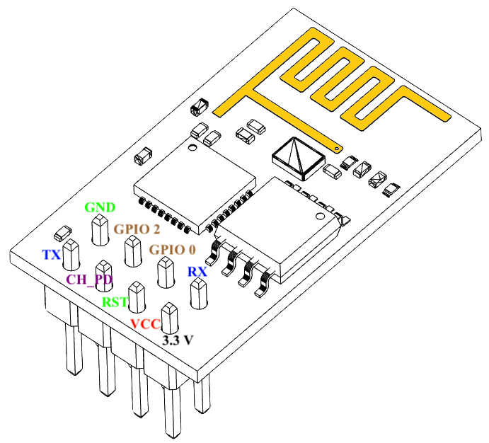
Pin Description
- VCC: Power supply pin of ESP-01 which can be supplied with 3.3V DC
- GND: Ground reference pin of ESP-01
- TXD: Used as UART Transmitter pin or GPIO 1
- RXD: Used as UART Receiver Pin or GPIO 3
- RESET: It is used to reset the Module and it is an active LOW pin.
- CH_PD: It is the chip enable pin which is an active HIGH pin.
- GPIO0: This pin serves two purposes. One is as General purpose Input/output and other is to enable Programming mode of ESP-01 when connected to ground
- GPIO2: This is a General purpose Input/output pin.
Skip to next step if you are not using ESP-01 Generic Module
Circuit Diagram of ESP-01 with Arduino for Uploading the Sketch
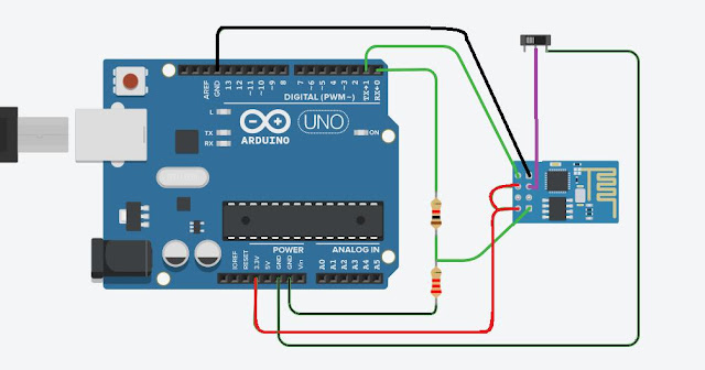
Connect the ESP8266 module with Arduino UNO as shown in the figure above, make sure that Rx is connected to Rx and Tx is connected with Tx as ESP-01 module is not 5 Volts tolerable, use voltage divider for Rx. When you want to program the board check first if GPIO0 is connected to ground otherwise you will not be able to upload any code to your ESP-01
Enable pin should also be supplied with VCC and optional for RST.
ESP8266 NodeMCU Board
 |
 |
ESP8266 NodeMCU is a Single chip microcontroller with on chip programmable ESP8266 Wi-Fi module with PCB antenna. It has 17 GPIOs GPIO0-GPIO16, but GPIO6 to GPIO11 are usually connected to the flash chip in ESP8266 boards. So, these pins are not recommended to use. It also has PWM functionality, IIC and SPI communication. The ESP8266 only has one GPIO that supports analogue reading with input voltage range of 0-3.3V. That GPIO is known as ADC0, and it is usually denoted by the letter A0 on the silkscreen. NodeMCU also supports Wi-Fi networking (can be used as an access point and/or station, host a web server), connect to the internet to fetch or upload data.
How to program NodeMCU using Arduino IDE ?
To use the Arduino IDE to program the NodeMCU, you must first install the board into the software.
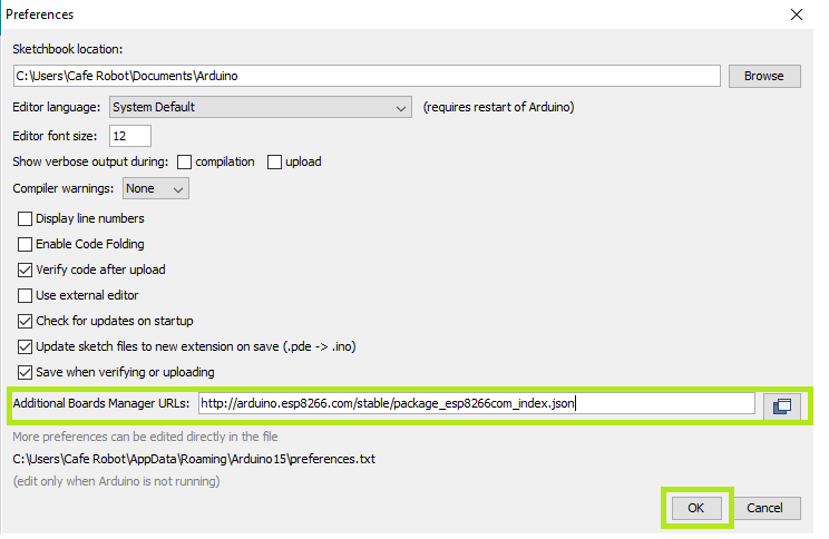
To do this copy the following code and follow the steps below:
http://arduino.esp8266.com/stable/package_esp8266com_index.json
Step1: Choose Preferences in the File menu and enter the copied code in Additional Board Manager URLs part. Then press OK.
Step2: Search the word ESP8266 in Boards>boards manager from Tools menu. Then install ESP8266 boards. After complete installation, you will see the INSTALLED label on ESP8266 boards.

Following these two steps, ESP8266-based boards such as NodeMCU will appear in your Arduino IDE boards list, and you can select your desired board to upload the code to.

To use digital pins, you must first select GPIO numbers. The D7 pin, for example, is designated as GPIO13. As a result, whenever you want to use D7 in your program, you should use pin number 13. You can also use pin D2 (GPIO4) as SDA and pin D1 (GPIO5) as SCL.
Setup Arduino IDE
Install Blynk library for arduino IDE following this link here
After installing suitable library open new sketch and copy the code given below:
Edit SSID, PASSWORD, Authentication Key with yours before uploading to your ESP8266 module
Don't just copy paste, try to improve the code and the code is self explanatory.
Setup Blynk App
Here, we are using BLYNK as our IoT platform to enable our device to communicate with cloud server. Install Blynk application in your smart phone and login or sign up.
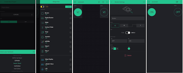
In Blynk terminal Click on, Create New Project and then choose NodeMCU in hardware devicesnow swipe left on screen and drag buttons from the widget section.
Now, click on the button and select the pin option and choose virtual pins V2 and V0.
Change your button to switch using slider
 |
|
Setup Blynk App |
On the top of your screen in the app, select settings to get your "authentication key" for this project and copy this key to apply in code. Press the play button to make your device receive signals from the cloud.
Integrate with IFTTT to add voice Google assistant
Go to IFTTT’s website and sign up to it using your Google or Facebook account
After Signing in click on profile from the header and select create .
Click on "this".

Search for google Assistant and select it. And then Click on Connect

At this point IFTTT will ask you permission to use your google account to add voice commands to it. Which you simply allow by clicking on "Allow".
Select the card that says “Say a simple phrase”.
Next, for the first text box type the phrase that you want to say to Google
Assistant. It can be anything such as “Turn on the Light”, “Turn on the fan” or anything you like.
For the next two text boxes, you write some other ways to say the first command. For example, if in the first text box you wrote “Turn on the
Lights”, then in the second and third text boxes you can write something like “Light up the room” or “Switch on the light”.
In the fourth text box type the reply that Google Assistant should respond with. For example, “Okay, Turning on the Light”.
Finally, click on ‘Create Trigger’.
Now click on "that"

and type webhooks, select it, and click connect. Webhooks will allow us to send commands to the Blynk Server.

Now, in the URL field type this URL:
http://188.166.206.43/ YourAuthTokenHere / update / DigitalPinToBeUpdateHere
we should use V2 and V0 as digital pins i.e GPIO2 and GPIO0.
Next, Select the ‘Method’ field as PUT
Select ‘Content type’ as Application/JSON.
For the ‘Body’ type this: [“0”]
Here ‘0’ means to turn on, so we are basically telling Blynk to turn on the relay that is connected to pin V2, which in our case is Bulb.
Now click on ‘Create Action’ and then Finish.
Similarly, we create another applet to turn off the relay. Repeat all the steps above.
For the ‘Body’ type this: [“1”].
Congrats, Now you've created a voice assistant based home automation system with Internet of things features embedded.
Circuit Diagram
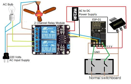
Note: Similarly looking at the above circuit you can make a connection with your NodeMCU board. In NodeMCU as there are more number of pins available you can attach more appliances and sensors too.
for using your existing switchboard as earlier with manual switches connect everything as shown in the image above and make sure connections are not loose.you can create your own PCB also as it will look more neat and clean.
We are using GPIO1 and GPIO3 as input pins connected to switches in the diagram above. Changing the values of these pins can change the status of relays, and the ESP-01 is also updating the Blynk server with the status of that appliance. As a result, that user will not be confused about the current status of that appliance.
Arduino Code
|
#define BLYNK_PRINT Serial #define RELAY_PIN_1 2 #define PUSH_BUTTON_1 1 #define VPIN_BUTTON_1 V2 #define RELAY_PIN_2 0 #define PUSH_BUTTON_2 3 #define VPIN_BUTTON_2 V0 #include <ESP8266WiFi.h> #include <BlynkSimpleEsp8266.h> char auth[] = "bccggllfyufjvbbm"; char ssid[] = "Free"; char pass[] = "12345678"; BlynkTimer timer; void checkPhysicalButton();/// int relay1State = LOW; int pushButton1State = HIGH; int relay2State = LOW; int pushButton2State = HIGH; // Every time we connect to the cloud... BLYNK_CONNECTED() { // Request the latest state from the server Blynk.syncVirtual(VPIN_BUTTON_1); Blynk.syncVirtual(VPIN_BUTTON_2); } BLYNK_WRITE(VPIN_BUTTON_1) { relay1State = param.asInt(); digitalWrite(RELAY_PIN_1, relay1State); } BLYNK_WRITE(VPIN_BUTTON_2) { relay2State = param.asInt(); digitalWrite(RELAY_PIN_2, relay2State); } void checkPhysicalButton() { if (digitalRead(PUSH_BUTTON_1) == LOW) { // pushButton1State is used to avoid sequential toggles if (pushButton1State != LOW) { // Toggle Relay state relay1State = !relay1State; digitalWrite(RELAY_PIN_1, relay1State); // Update Button Widget Blynk.virtualWrite(VPIN_BUTTON_1, relay1State); } pushButton1State = LOW; } else if (digitalRead(PUSH_BUTTON_1) == HIGH) { // pushButton1State is used to avoid sequential toggles if (pushButton1State != HIGH) { // Toggle Relay state relay1State = !relay1State; digitalWrite(RELAY_PIN_1, relay1State); // Update Button Widget Blynk.virtualWrite(VPIN_BUTTON_1, relay1State); } pushButton1State = HIGH; } if (digitalRead(PUSH_BUTTON_2) == LOW) { // pushButton2State is used to avoid sequential toggles if (pushButton2State != LOW) { // Toggle Relay state relay2State = !relay2State; digitalWrite(RELAY_PIN_2, relay2State); // Update Button Widget Blynk.virtualWrite(VPIN_BUTTON_2, relay2State); } pushButton2State = LOW; } else if (digitalRead(PUSH_BUTTON_2) == HIGH) { // pushButton1State is used to avoid sequential toggles if (pushButton2State != HIGH) { // Toggle Relay state relay2State = !relay2State; digitalWrite(RELAY_PIN_2, relay2State); // Update Button Widget Blynk.virtualWrite(VPIN_BUTTON_2, relay2State); } pushButton2State = HIGH; } } void setup() { // Debug console Serial.begin(9600); Blynk.begin(auth, ssid, pass);
pinMode(RELAY_PIN_1, OUTPUT); pinMode(PUSH_BUTTON_1, INPUT_PULLUP); digitalWrite(RELAY_PIN_1, relay2State); pinMode(RELAY_PIN_2, OUTPUT); pinMode(PUSH_BUTTON_2, INPUT_PULLUP); digitalWrite(RELAY_PIN_2, relay2State); timer.setInterval(500L, checkPhysicalButton); } void loop() { Blynk.run(); timer.run(); } |