

As a kid, I was always fascinated by the RC cars. Nowadays you can find many tutorials to make cheap Bluetooth controlled RC cars yourself with the help of Arduino. Let's take it a step further and use our practical knowledge of kinematics to calculate the distance covered and the velocity of the bot.
Step 1: Finding the Required Parts to Make to Project
- Microcontroller: If you are a beginner try using an Arduino. Well, I am using Arduino Uno. Buy link for the Arduino Uno.
- Motors and encoders: For this project, I am using 150 RPM side shaft geared motors with an inbuilt encoder to calculate turns. if you are unable to find such motors can refer to simple dual shaft bo motors and you will have to buy encoders for the BO motors. you can buy dual shaft BO motors | single encoders.
- Motor driver: You will need a motor driver to run the motors as most microcontrollers cannot supply that much voltage. I am using an L298N which you can refer here to buy from here.
- CHASSIS: For chassis and tires, you have to buy a specific one for the motors you are using. to buy chassis for BO motors you can refer to this link.
- Bluetooth module(HC05): To connect Arduino with our smartphone we need a device for Bluetooth communication. here is where HC05 comes in handy. Buy link for HC05.
- Jumper wires: We all need jumper wires to connect stuff. If you are a newbie you would need a bunch of these for different projects. you can buy some from here:- Jumper wires Male to Female | Jumper wires Female to Female | Male to male.
- Battery: Well I am using a 12v lipo battery for this project. if you don't have that you can always shift to generic 12v lithium-ion batteries. Or if you are using 9V BO motors you can even use a simple 9V battery. But be careful to check your motor specification before buying the battery as you can damage the motor if you supply higher voltage than the motor capacity. To buy 9v battery refer here.
-
Breadboard/prototyping board: You will need something to connect all the wire. Here breadboard will come in handy. buy link for Breadboard | prototyping board.
Step 2: Setting Up Your Chassis

If you are working with pre-built chassis you won't have to worry about with stuff.
So as I didn't have the specific pre-built chassis for my motors so I had to build one myself. I chose the acrylic sheet for the base as it is lightweight and easy to work with and used standard clamps to mount the motors and at last screw the chaster wheel at the bottom to support the bot.
Step 3: Wiring Up the Motor Driver
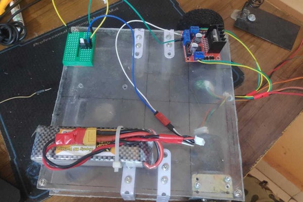

To supply sufficient juice to motors we need to set up the motor driver.
- First, screw the +ve and -ve poles of the motor to the PTR connector of the motor driver.
- Then to power, the motor driver screws the +ve of the battery to 12v port and -ve to the GND port of the motor driver.
-
Put the input pin of the motor driver to the PWM pin of Arduino as of your choice. REMEMBER to change to motor pins in the code accordingly.
- Add a switch between the +ve of the battery and the motor driver otherwise, you will have to keep disconnecting the battery when you are not using it.
- Get 2 wires from the 5v and GND of the motor driver to the breadboard so you can power Arduino as well as other devices.
Step 4: ENCODERS Setup

As you can see the encoder is inbuilt with the motor.
- M1 and M2 are the +ve and -ve of the motor which goes into the motor driver
- Attach to 5v and GND of the encoders to the 5v and GND of the breadboard to power the encoders
- A and B are for the encoder output pins which we will attach the pin 2 and pin 3 of the Arduino
Step 5: Wiring Up the Arduino and the Bluetooth Module


- Attach the GND and 5v from the breadboard to Vin and GND of the Arduino to power the Arduino.
- Do the same with the Bluetooth module to power it as well.
- Attach the TX and RX of the Bluetooth module to the 0 and 1 pins of the Arduino. The 0 and 1 pins of the Arduino are the designated pins for serial communication so be careful while uploading the sketch to the Arduino as you may need to disconnect the TX pin as Arduino can use only 1 serial communication at a time. You can avoid this hassle by introducing the Software Serial library in the code
- Attach the encoder pins to 2 and 3 pins of the Arduino. Pin 2 and Pin 3 are designated pins for the interrupts. For more information on the interrupts refer here. you may not need interrupts if you are using encoder disk with fewer pulse lines.
Step 6: Attaching the Electronics to the Bot

You can use screws to mount the electronics on the bot otherwise as the bot moves the electronics tend to fall off.
Well, I didn't had that small screws to mount the electronics so I went to hot glue the electronics on the base itself.
Step 7: Building Up the App to Control the Bot


To make the app I used the MIT app inventor which is really easy to use and convenient for beginners. Believe me, I am not an android developer and the idea of building an app scared me. But with this, I just learned as I made the app.
For the designer part, I am leaving that to you. Customize the way you like it.
You can refer to the images to make to the backend part.