Many people have queries regarding calculating the wattage of a Zener diode or selecting the register in the circuit so this blog will clear those doubts. This blog is the continuous blog of the series of Diodes so if you wish to read about any other diodes or basic's of diode then you may visit our website(click for visiting the website).
How does a Zener diode regulate voltage?
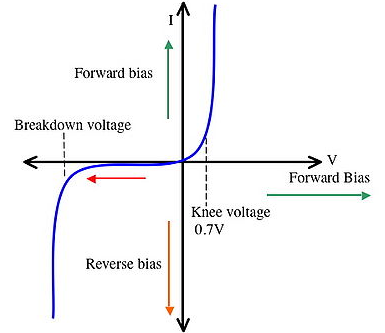
Zener diodes are commonly used as voltage references in small circuits. When a Zener diode is reverse biased and placed in parallel with a variable voltage source, it conducts when the voltage equals the diode's reverse breakdown value.

Zener Diode As a Voltage Regulator
A single Zener diode and a resistor make up the simplest basic Zener diode circuit. The reference voltage is provided by the Zener diode, but a series resistor is required to restrict the current entering the diode; otherwise, a significant amount of current would flow through it, potentially destroying it.
The value of the resistor in the Zener diode circuit should be calculated to give the required value of current for the supply voltage used.

Let’s take the case where a Zener diode circuit is used to supply a regulated 5.1 Volt, input voltage supply of 12 volts. The following easy steps can be used to calculate the resistor required and the Zener diode.
So, Vin = 12V
Vout= 5.1V
Step1: Calculate the difference in voltage across the series resistor
R = (Vin-Vout) / I , formula for finding the resistance value.
Vr = Vin - Vout
12 - 5.1 = 6.9 volts
So, the voltage across the resistor is, Vr = 6.9V
Now let’s choose the current that should be running in the circuit.
So, I = 90mA, max =110mA
Step2: Determine the series resistor's value. The voltage drop across it (Vr) and the total current through it can be calculated using Ohms law:
R = Vr / I
R = 6.9 / 110 mA = 0.0627 k ohm
So, R =62.7ohm
The nearest value resistor is 62 ohms
Step3: Determine the series resistor's wattage (Pr). This can be calculated using the previous values for the current through the resistor and the voltage across it:
Pr = VI
P = 6.9V x 110mA = 759mW
So, Pr = 759mW
The resistor dissipates the level of heat. A 1watt resistor should be adequate for this.
So, the Resistor which will be used in this circuit will be, 62ohm 1 Watt
Step4: Check the power dissipation of the Zener diode. The power dissipation at 110 mA current and a voltage across the power dissipation is:
Pz = Vz x I
P = 5.1v x 110mA = 561mW
So, Pz = 561mW
As per the values obtained, the selected Zener Diode is 1N4733A, the wattage of it is 1300mW

So this way we could get the values as per the requirement of the voltage at the output and varying the current in the circuit. After getting the values it will be easy for us to choose a Zener diode.
At last, if you wish to buy any of the resistors or the Zener Diode then you may click on their names present down.
It is extremely simple to measure resistance and voltage in a circuit using a Multimeter.
Buy Online DT830D Digital multimeter datasheet at Best Price in India from HNHcart.com for measuring two or more electrical values such as voltage, current, and resistance.

